
|
|
Truespace5 TipCourtesy of Paul Texturing and applying UV's in Truespace can result in objects with excessive verts in the model if one doesn't know what is going on. Also using different Shader Attributes values on the same object clump can cause more verts than what TS reports in the Object Info box when converted to rwx (at least using Cobdump). If at all possible you should never use different surface settings (shader attribute) values on faces of the same clump. As far as texturing and applying UV's there is a little trick that can result in less verts while getting the same look in many cases. This is how it works. We will us a Cube primitive as an example. A cube normally as 8 verts. I am using the wood paneling you see in the jpg as my texture. Only certain types of textures will work with this method of keeping the verts down. Usually woods and bricks are good and some others but it just depends on the texture. If you apply a texture using Cube UV projection to a Cube you will end up with a Cube in AW that now has 20 verts instead of 8. In some cases you can get this back down to 8 verts or if the top and/or bottom faces of the Cube are important and will be visible then you can still in many cases get the verts down to 16 or 12. The illustration demonstrates how in TS 5. 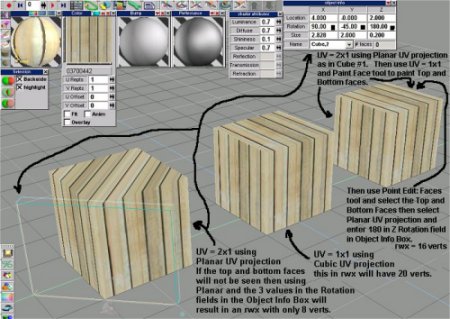 For an 8 vert Cube where the top and bottom faces will no be visible you can apply the texture (again not all textures are suitable) with UV values of U=2 and V=1 using the Paint Object tool. Then choose the Planar UV projection tool and in the Object Info Box in the Rotation fields, type 90 in the X box, 180 in the Z box, and then -45 in the Y box. You will see the UV Outline frame at a 45 degree angle as in the 1st Cube in the illustration and you will not the 4 sides on Cube #1 look the same as a UV ox 1x1 applied on Cube #2 using Cube UV projection. Note that the top (and bottom) texture of Cube #1 is now messed up but since we said that in this case we are assuming the top and bottom will not be seen and thus unimportant that does not matter and so we will end up with a cube that has only 8 verts and the sides look the same as the 20 vert Cube #2. This method can be very useful for thick walls and post or square columns and such thing where the top and bottom will or may not be seen ( maybe have something else covering them up for instance). Now if we need the Top to be visible and look correct wen can take what we did above and then change the UV values to U=1 and V=1 and use the Paint Face tool and paint the top face with the 1x1 texture. Then we use the Point Edit:Faces tool and select the Top face of the cube. Next we choose the Planar UV projection tool again and this time we just type 180 in the Z rotation field in the Object Info Box leaving the X and Y boxes alone. This results in the sides and top (see Cube #3 in the illustration) looking the same as the Cube #2 but now we will have a cube that has 12 verts (still better than 20). If both the Top and Bottom are both important then use the 8 vert method then paint a 1x1 UV texture on both the top and bottom faces and then use Point Edit and select both the Top and Bottom faces and then choose Planar UV and enter 180 in the Z Rotation in Object Info and you have a Cube (#3 again) that looks just like Cube #2 but has 16 verts instead of 20.
|
| Active Worlds | Newsletter Home | Newsletter Archive | Contact Us | Disclaimer |